About this deal
If you buy your own FTDI chip, go for something that has two serial ports, e.g. FTDI FT2232H, those are often used as JTAG interface with an additional serial port, too. As an Arduino-phil I use the ESP8266 Core from GitHub to adapt the Arduino IDE to the ESP8266. It uses a somewhat different tool chain to compile the Arduino C code into binary files executable by the ESP8266, but the Arduino IDE and most libraries are the same. The only stumbling points are:
Often the FTDI based ones are preferred. The FTDI chip is very expensive in comparison with other USB to TTL bridges, but they are often preferred. So look for FTDI when searching USB to TTL. Often FTDI ones use fake clones instead of the genuine and expensive FTDI, so if it's too cheap then it's probably not genuine FTDI. Turns out that the driver isn’t signed and in Yosemite, driver files must be signed to be used. There’s a command we can issue to bypass this. Global variables use 9 bytes (0%) of dynamic memory, leaving 1,015 bytes for local variables. Maximum is 1,024 bytes.You want to use unidirectional voltage level translators or isolators for UART and SPI, and not bidirectional ones, as the latter tend to have glitches (in the low level signal part, when the direction sensing circuitry isn't sure of what is going on) in this kind of use that can cause transmission errors. So, I'd say forget TXB chips, and all bidirectional voltage level conversion chips. I wanted to try echolink and I found that this interface worked perfectly except Echolink likes the serial PTT option. But it doesn’t end here! That’s were the Power Cutter comes in. Thanks to Talpa PCB retrace of the BTE13-010 I was able to elaborate an evil power saving plan:
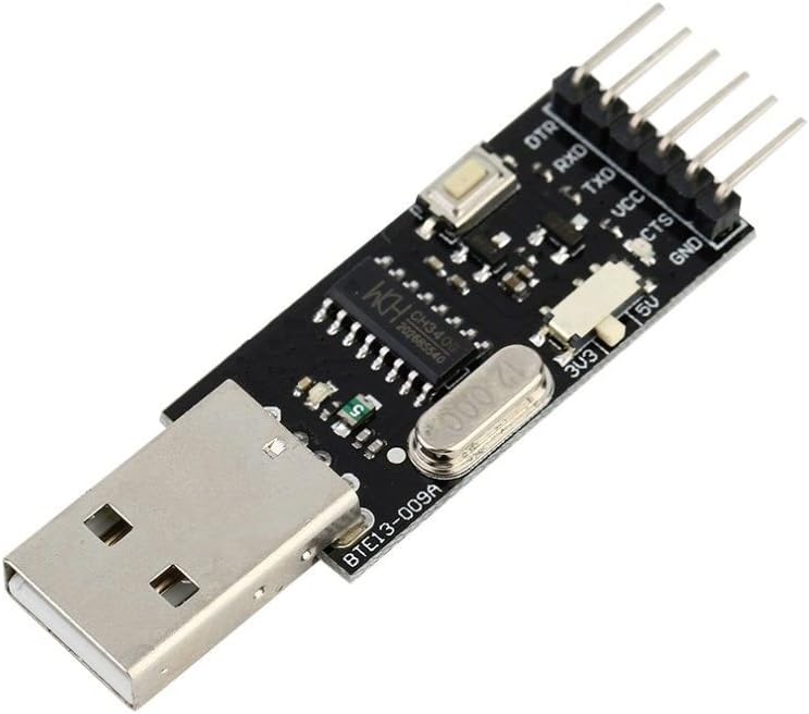
Another alternative is to buy the FTDI chip from a reliable vendor, so to be sure it is genuine, then wire your own. Here's an example of a FT232RL wired by hand to a 0.1 inch perfboard. Before connecting the Serial – USB converter, make sure that the switch is positioned on the appropriate voltage value which can be 3.3V or 5V depending on the model of your Arduino. Ours works at 5V and 3.3V interchangeably. Bus 002 Device 002: ID 174c:55aa ASMedia Technology Inc. Name: ASM1051E SATA 6Gb/s bridge, ASM1053E SATA 6Gb/s bridge, ASM1153 SATA 3Gb/s bridge, ASM1153E SATA 6Gb/s bridge The analogue header doesn’t fit because of the reset button. Use sandpaper to make the analogue header thinner. I have that model, too. That board is a mistake by design. It was very infuriating to find out the power supply was changing, while the levels on the data pins voltage were always 0..5V.The main difference between HamComm and FLDigi is that FLDigi can use a tone on the right channel to key the rig eliminating the need for a serial port to drive a relay that Hamcomm used. Before starting, we specify that this tutorial can be used to learn how to install the drivers of the CH340G module (Serial – USB converter), on which the communication between the Arduino mini and the PC is based.
The power_saving_init() should be the first thing to be called at setup(), it will initialize all your pins to LOW. power_saving_sleep() will put everything to sleep, and wake up every 8 seconds. With these two, with the regular board (no bootloader modifications, with the power regulator on, etc) when sleeping I was able to achieve 3.24mA of power consumption, which is already pretty good considering it was draining about 10.2mA when fully powered on in the first place. The first one I killed when I used a USB TTL adapter that I believe kept the TTL signal level at 5V even when selecting 3.3V. the connector to be soldered on the part of the analog inputs is too wide, thin it slightly by rubbing it on sandpaper As long as your computer can see other devices plugged into the same USB port and assigns them a comm port number (each number is unique to THAT device) then it is either the cable or the board on the Ortur. soldering material and equipment (in this regard you can watch our tutorial Yet another tutorial on how to solder)The NODEMCU “Arduino friendly” pin names (D0 thru D8, plus RX and TX) don’t correspond with the actual ESP8266 GPIO pin numbers, so you have to make special arrangements to map the “D1”, “D2”, etc names to the actual GPIO pin numbers. There are a few ways to do this. Arduino clones need specific drivers, different from the standard ones that come with the Arduino IDE As said in the introduction, in this step we won’t explain how to solder because it would make the tutorial too long and, above all, because we already covered this topic in our first tutorial. So, take a look at it if you want to know more about soldering. As said you can try rebooting your computer and see if that helps…I never had to myself for my diode laser but…I have had to for other driver installs so…can’t hurt. Computers are funny things. While Arduino is placed on the breadboard, only solder the four vertex joints. Why only four vertex? Because breadboard is made of plastic and if you accidentally hit it with your iron solder tip you’ll damage it.
 Great Deal